LED Music Visualizer
I’ve spent the past few days finally working on the music visualizer that I’ve wanted to make for well over a year now. While there are a few issues, it still looks beautiful, so I decided to call the first version of this project “done”.
As the video shows, the visualizer doesn’t require much hardware knowledge. So long as you have the equipment to do some soldering (or at least a friend who does), this project is entirely viable.
Materials
- 1x Arduino UNO - $20-$30
- 1x ShiftyVU shield - $19.99
- 2x LPD8806 LED strip - $29.99/ea.
- 1x 5V 2A power supply - $9.95
- 1x 2.1mm jack to screw terminal block converter - $2.00
- 1x 4-pin JST SM Plug - $1.50 (optional)
- 1x 3.5mm stereo Y splitter - $3-$5
- 1x 3.5mm stereo cable - $3-$5
Setup
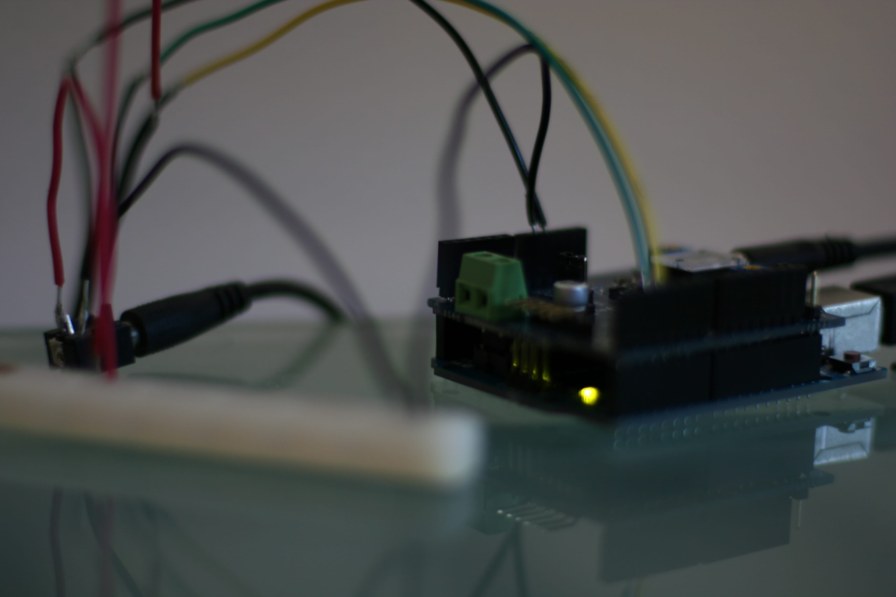
- Solder on the header pins that came with the ShiftyVU shield and fit on top of Arudino.
- Replace the audio output from your computer with the Y splitter. Plug your normal output as well as the extra cable into the splitter. The extra cable plugs into the ShiftyVU shield.
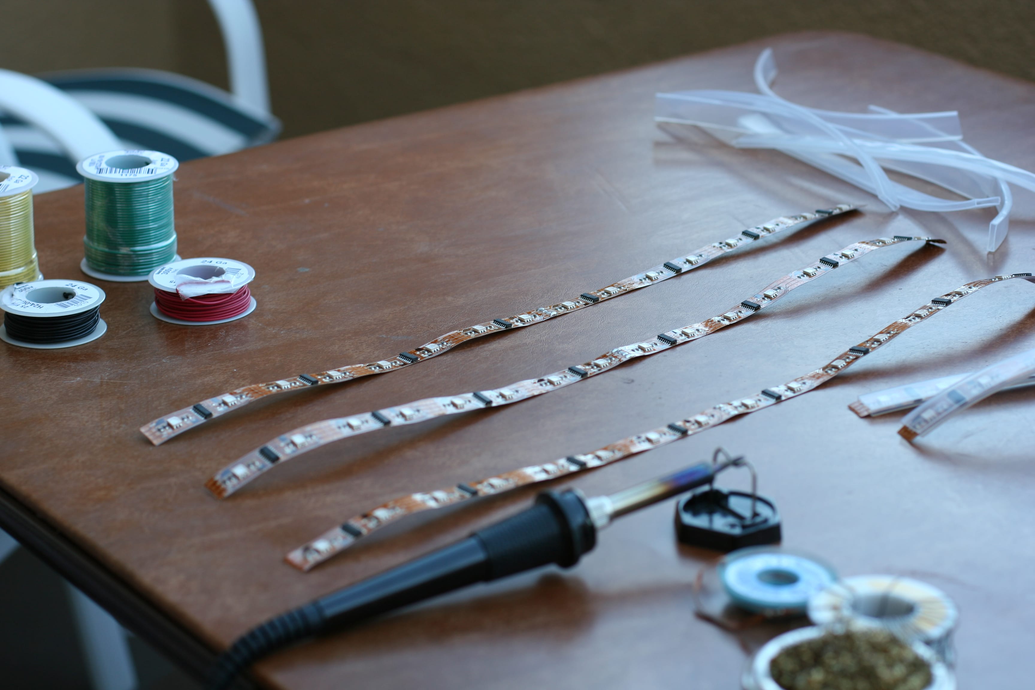
- Desolder the LED strips from each other. They should come in sets of 16 LEDs. Cut each one in half for 8 LEDs per strip.
- Lay out the strips where you want them to be and measure how much wire you’ll need. The bars don’t necessarily need to be soldered in the same direction. In my case, every other strip is backwards. This is very easy to account for in software.
- Cut and strip all the wire you need. Solder the LED strips together with the wires, making sure you’re always connecting an output to an input (marked by “CO/DO” and “CI/DI” respectively). Here’s the Adafruit article on wiring this particular LED strip.
- Optionally, solder the JST SM plug to the input of the first strip. That
way you can unplug the LEDs if it’s ever necessary.
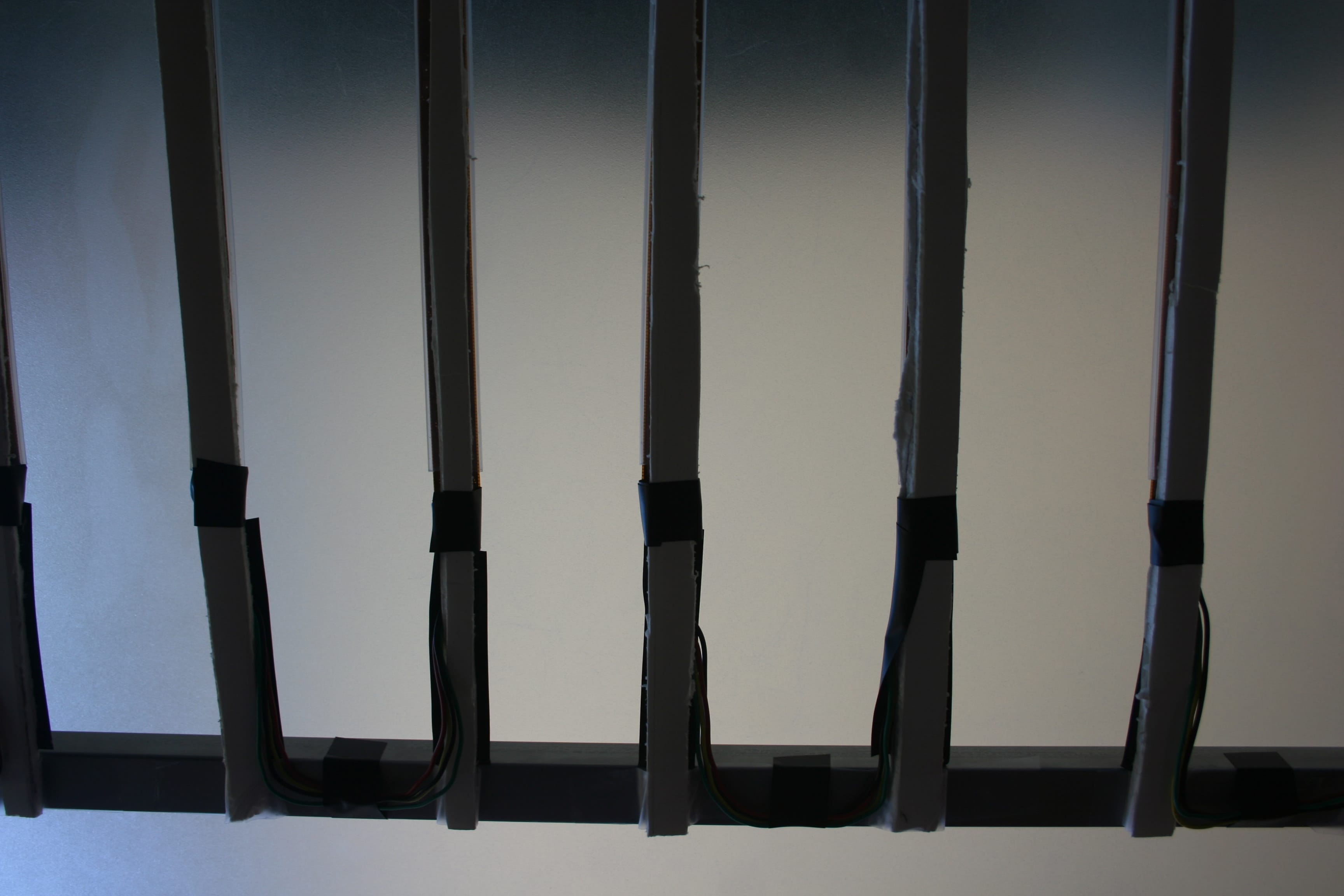
- Plug in the power supply to the 2.1mm jack to screw terminal block converter. Attach a red wire to the + block and a black one to the - block. The red wire can go directly to the +5V on the LEDs, but the black one must be in a common ground with the Arudino. Luckily, the Arduino has 2 GND ports, so plug the black wire to one of those ports, and then run another black wire from the other GND pin to the LED’s GND wire.
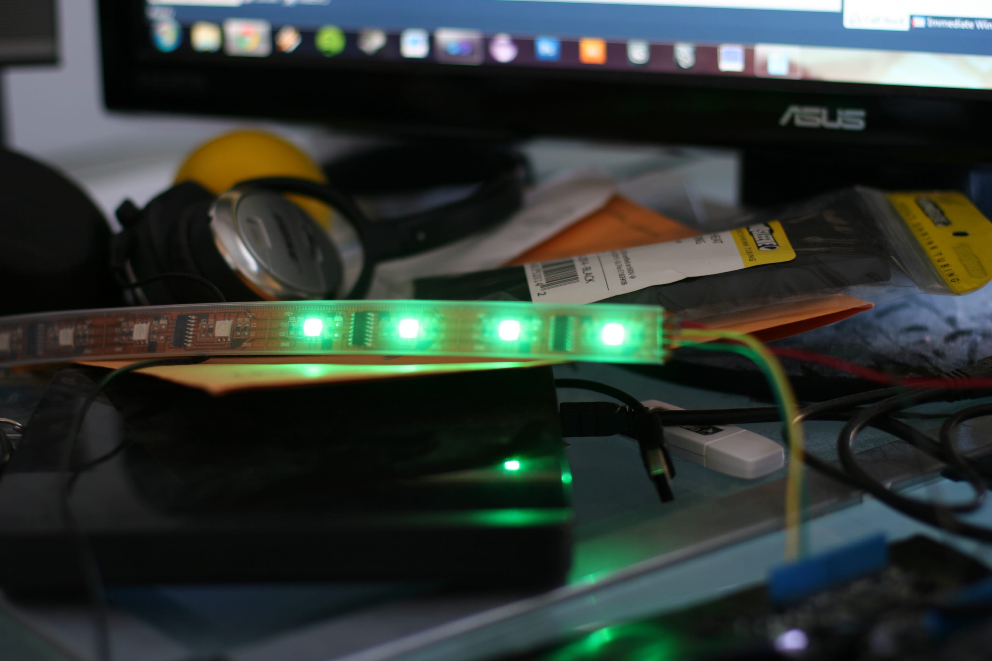
- Plug the data wire (DI, green wire) into the Arduino’s digital pin 2 and the clock wire (CI, yellow wire) into digital pin 3.
- Download the source code from my GitHub repository, follow the installation instructions, then upload it to your Arduino.
- Put on some music and stare!
In the next version of this project, I’m planning on building a small circuit to read the audio in myself. As I explain in the video, the ShiftyVU does some filtering of the audio that doesn’t work well with spectrum analysis, but is good enough to make something visually pleasing.
Source Code
In case you glanced over the setup section.
Progress
Here are some of the pictures I posted on Facebook and the videos I posted on Instagram as I was working on the project.
